Hey there, it’s Mia from the C&I energy storage team— I’ve spent the last five years walking jobsites with contractors, field engineers, and plant managers who thought a "good flat patch of concrete" would work for their commercial and industrial (C&I) energy storage system. Spoiler: 90% of the time, those sites missed critical foundation requirements that led to delays, safety scares, and extra costs down the line. Today, I’m breaking down exactly what your installation site foundation needs to check off before we even ship the battery racks—no jargon, just real lessons I’ve learned in the field. C&I Energy Storage
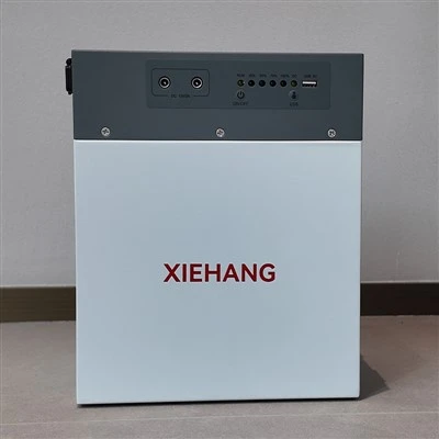
First, let’s make sure we’re on the same page about what we’re installing. C&I energy storage isn’t the tiny residential unit in your neighbor’s garage. These are systems ranging from 500 kWh (for a small retail park or warehouse) up to 10 MWh (for a manufacturing plant or university campus) — we’re talking steel racks holding heavy battery modules, inverters that hum like a semi-truck idling, and cooling systems that need stable power to keep everything running. That means the foundation isn’t just a place to set the equipment; it’s a structural backbone. Skipping steps here isn’t just a hassle—it’s a safety risk, and a costly one. Last year, we worked with a food processing plant that tried to use their existing warehouse pad foundation for a 2 MWh system. They didn’t test the soil bearing capacity, and three months after installation, one corner of the pad settled 2.5 inches. That cracked the battery cabinet’s frame, triggered a shutdown, and cost them $120k in lost production plus $80k to repair the foundation. Don’t be that guy.
Let’s start with the non-negotiable structural requirements, because if this is off, nothing else matters. First is soil bearing capacity testing. Most contractors or site teams think they can skip this—“the ground here is solid,” or “we built a storage shed here last year.” But C&I energy storage foundations need to support dead load (the weight of the batteries, racks, inverters, and cooling gear—roughly 150-200 lbs per square foot for medium-sized systems, higher for larger ones) plus live load (maintenance workers walking on the unit, tools, maybe a small forklift for battery swaps). Soil bearing capacity tests aren’t guesswork—they’re core samples, at least 10 feet deep (we always recommend 15 feet for sites with a history of soft soil, like near lakes or former wetlands). The minimum required bearing capacity we work with is 2,000 psf (pounds per square foot). If your soil comes back lower than that, you have two options: 1) install deep foundations (piers or piles) that extend down to load-bearing soil, or 2) do soil stabilization (mix in gravel, lime, or concrete to densify the top layer). I can’t tell you how many times I’ve had to push back on a client who said, “We can just add more concrete to the pad.” That doesn’t fix soft soil— the pad will still settle.
Next, pad design and dimensions. This depends heavily on the system size, but general guidelines apply. For ground-mounted systems (the most common for C&I, since roof-mounted has its own set of issues we’ll touch on later), the concrete pad needs to be a minimum of 6 inches thick. If you’re in an area with high seismic activity (think California, the Pacific Northwest, parts of the Southeast) or heavy frost lines (like the Upper Midwest), you need to beef that up to 8 inches, plus add rebar grid reinforcement—#4 rebar at 12-inch intervals both ways is standard. Why rebar? It prevents cracking if the pad settles unevenly or shifts during an earthquake. Dimensions: the pad needs to be at least 2 feet larger on all sides than the battery enclosure, to leave space for cable routing, maintenance access, and fire suppression equipment. For example, if your battery cabinet is 20ft x 10ft, the pad needs to be at least 24ft x 14ft. Also, the pad must be level to within 1/4 inch over a 10-foot span. I know that sounds precise, but unlevel pads cause major issues: battery rack frames can warp, which misaligns connections and increases fire risk, and cooling systems can’t circulate air properly if the unit is tilted. We always recommend using a laser level to check this—eye-balling it with a tape measure will get you into trouble.
Now, if you’re considering a roof-mounted C&I system, the foundation rules are different, no pun intended. Roof foundations are structural support added to the existing roof, not ground soil. First, you need a roof load capacity test. Most commercial roofs are designed to support their own weight plus some live load, but adding a 500 kWh system can add an extra 100,000 lbs or more. We always work with a structural engineer to calculate the live load the roof can safely handle—including the additional weight of maintenance teams and equipment. Also, roof-mounted systems need their own level support frames (usually steel, not concrete) that are fastened directly to the roof’s trusses or load-bearing points, not just the roof membrane. We saw a bad example of this a few years ago: a retail chain in Chicago put a 1 MWh system on their mall roof, attached it with generic brackets that only secured to the roof membrane. A wind storm came through, and the brackets pulled loose, taking half the battery array with them. That’s why we require roof anchors tied to the trusses, not just the surface.
Now, we can’t ignore environmental and regulatory requirements—these are often the reason projects get delayed 2-3 months, so don’t leave them for last. First, site grading and drainage. The foundation pad must be graded to slope away from surrounding ground, not toward it. That means water won’t pool around the base of the batteries, which is a huge safety hazard. Pooled water can seep into electrical connections, cause corrosion, and even lead to short circuits. We recommend a 2% slope for the pad, which is gentle enough that it doesn’t affect levelness for the equipment, but steep enough to drain water. Also, if your site is in a flood zone (FEMA has flood maps for every area), the foundation pad needs to be at or above the base flood elevation (BFE) for your region. If it’s not, you’ll need to elevate the pad—either by adding piers to lift it above BFE—or get flood insurance, which is way more expensive long-term. Last year, a client in Houston tried to install a system on a pad that was 1 foot below BFE; we had to pause the project for a month while we worked with a civil engineer to raise the pad’s elevation, because their insurance wouldn’t cover any water damage otherwise.
Then there’s utility and setback requirements. Every municipality has rules about how far a C&I energy storage system can be from property lines, power lines, or other structures. Most places require a minimum 10-foot setback from property lines, and 25 feet from public roads or utility lines. That’s not just a random rule—it’s for safety: if there’s an electrical fault or fire, emergency teams need space to work, and the system’s noise and ventilation can’t disturb neighbors. We always check local zoning codes before we even quote a project, because some areas have restrictions on ground-mounted energy storage (they might consider it a “commercial structure” that needs special permits). Also, you need to confirm there’s enough space for utility connections: the main power lines need to run within 50 feet of the foundation pad, usually, to avoid extra trenching costs for cable.
Wait, I also want to talk about a requirement that’s easy to overlook, but has caused more headaches than I can count: accessibility and clearance for maintenance. Your foundation pad needs to have enough space around it for a service truck to pull up and access the equipment. That means at least a 12-foot wide clear path from the nearest public road to the pad, no parked trucks, fences, or trees blocking it. And around the pad itself, you need at least 3 feet of clearance on all sides for technicians to walk, replace batteries, and access inverters. A few months ago, we worked with a manufacturing plant that built their pad right next to a storage shed, leaving only 18 inches of space on one side. When we tried to service the inverter, the technician couldn’t get the large inverter module out through the side door—they had to remove part of the shed, which cost the plant an extra $5,000 and delayed their grid interconnection by a week. Don’t let that be you.
Now, let’s talk about pre-installation inspections—this is a step we require for every project, no exceptions. Before we deliver the equipment, our field team does a full foundation audit, checking every single requirement we’ve talked about: soil test results, pad levelness, drainage, setbacks, accessibility. We bring a laser level, a tape measure, and a soil moisture meter (wait, another thing! We also check soil moisture, because overly wet soil can change bearing capacity if it rains after the test—so we do a follow-up check a week before installation). If anything is off, we flag it immediately, and work with the client’s contractor to fix it before we ship the batteries. We’ve never regretted doing this— it’s saved our clients hundreds of thousands in repairs and delays.
I want to be clear: these requirements aren’t arbitrary. They’re based on years of real-world experience, plus industry standards from organizations like the Fire Protection Association (NFPA) and the Energy Storage Association (ESA). NFPA 855, the standard for energy storage systems, mandates foundation strength, drainage, and setbacks to prevent fires and structural failures. ESA’s Site Preparation Guidelines add the soil testing and levelness requirements we talk about. Skipping these isn’t cutting costs—it’s risking safety, downtime, and extra expenses that will far outweigh the cost of preparing a proper foundation.
Let me wrap this up. When you’re planning a C&I energy storage project, the foundation isn’t just a step in the construction process—it’s the foundation of a reliable, safe, long-lasting system. You need to test soil bearing capacity (minimum 2,000 psf at 10ft deep), build a level concrete pad (6-8 inches thick, rebar-reinforced, level to 1/4 inch over 10ft), plan drainage and elevation (2% slope, above BFE if in a flood zone), comply with local setback and zoning rules, ensure enough maintenance access, and do a pre-installation audit before equipment arrives. Every step here is designed to keep your system running for 15-20 years, not just the first three months.
If you’re in the planning phase of a C&I energy storage project and want to make sure your foundation is set up for success, don’t leave it to chance. Our team has worked on hundreds of C&I projects across the country, and we can walk you through site requirements, connect you with trusted local engineers and contractors, and help you avoid the costly mistakes I mentioned today. Reach out to us to start a conversation about your project—let’s build something reliable together.
C&I Energy Storage References:
National Fire Protection Association. (2023). NFPA 855: Standard for the Installation of Stationary Energy Storage Systems. National Fire Protection Association.
Energy Storage Association. (2022). C&I Energy Storage Site Preparation Guidelines. Energy Storage Association.
American Society of Civil Engineers. (2021). Soil Bearing Capacity for Civil Infrastructure Projects. American Society of Civil Engineers.
FEMA. (2023). Flood Map Service Center (FMSC) Base Flood Elevation Data. Federal Emergency Management Agency.
Zhejiang Xiehang New Energy Equipment Co., Ltd.
As one of the most professional c&i energy storage manufacturers and suppliers in China, our products have good reputation in the market. Please erst assured to wholesale custom made c&i energy storage from our factory. If you have any enquiry about cooperation, please feel free to email us.
Address: No.5 Hechen Road, Zhouwangmiao Town, Haining, Jiaxing City, Zhejiang Province, China
E-mail: dan.wu@xiehang.net
WebSite: https://www.shineonpower.com/
